How to
Automatic air objective change
The QLS-scope can be equipped with up to 4 air objectives that can be used between 1x, 2x, 4x, 5x, 7.5x and 10x. The change between objectives can be done automatically through the software, just picking the desired objective from an available list.
Sample handling
The goals of any sample handling system for Light Sheet Microscopy are:
- Hold any size of sample
- No extensive manipulation of the sample (especially important for live or soft clarified samples)
- Possibility to recover the sample intact in case of need for feature measurements
- Possibility to make 360o images (hence the holder must not hide part of the sample from the illumination or detection path) in order to achieve isotropic resolution
- Capability to keep the sample still (so it does not shift when the holder is displaced)
- Be able to image samples in any solvent (water or organic based)
We have achieved all these, just by using tubes of different diameters and different materials:


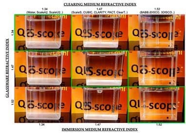
The internal diameters of the tubes range from 1mm to 20mm and allow the placement of any sample while keeping it well supported during the tube movements. They are made with materials matching the most common solvents (water, SCALEA2, ScaleU with IR 1.34 – CUBIC, SCALES, Clarity, ClearT, PACT with IR 1.47 – BABB, IDISCO, 3DISCO with IR 1.52). As you can see in the image above, when a tube made of a suitable diffraction index material is used, the tube stops generating distortions in the image (images in green). Using tubes allows us to see the sample at 360º and the sample can be inserted and removed easily. Our system is very open so other modes of sample support can also be used (e.g. agarose embedded samples, sample fixed on slides, etc.). In the following video you can see how easy it is to place a sample in the sample support:
Shadows removal
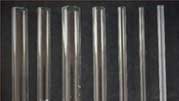
One of the most common problems in light sheet microscopy is the appearance of shadows due to areas of the sample that are not transparent. This problem is much more pronounced in live samples with opaque organs such as the eyes. A variety of physical LSFM implementations attempt to access the sample from different angles to “see around” attenuating features. Multi-view (MuViSPIM), multidirectional SPIM (mSPIM) and multi-arm LSFM systems can all reduce attenuation artifacts by illuminating and/or detecting light from different orientations and “bypass” the attenuating features of the sample. However, these are not universal solutions. A single attenuating region can be avoided by imaging around it, but more complex spatial distributions of absorbing materials can produce collections of shadows that cannot be removed in this way:
Our QLS-scope uses an optical setup that, without any mechanical movement, can create hundreds of angles of the light sheet that strike the sample from hundreds different angles and achieve the elimination of shadows even on the most complex samples.

Reduced need for data storage
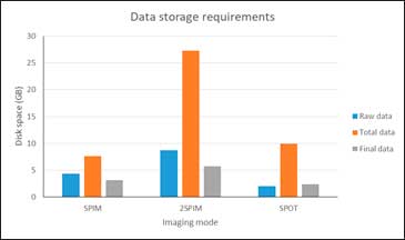
Light Sheet microscopes generate a large amount of data that requires large storage capacity and access for future retrieval and reprocessing. In a study carried out, comparing the amount of data generated by a Light Sheet microscope and a confocal microscope, during a continuous use of both devices for 24 hours, the amount of data in Light Sheet microscopy is 3 orders of magnitude greater than that of a confocal microscope. Our measurement mode, called SPOT, not only achieves unsurpassed axial resolution, compared to a conventional Light Sheet microscope, but also generates less data. A single angle SPIM usually has more than 800 images (z stack) in order to have an acceptable axial resolution. If we add the need to stitch several fields of view to cover the whole sample, that number is multiplied (e.g. 3×3). If you also choose to measure and later combine SPIM mosaic images and at different angles to obtain better axial resolution, the amount of data skyrockets. With our SPOT measurement mode, the number of images is always the same and coincides with the number of angles we have measured (e.g. 500). In the table below you can see a comparison between the original data, the processing data (which is deleted at the end of the processing) and the final data for a SPIM of a single angle, a 2 angle SPIM and a SPOT:
Although the need for data storage is not ruled out, with SPOT mode, less hard disk capacity is required.
