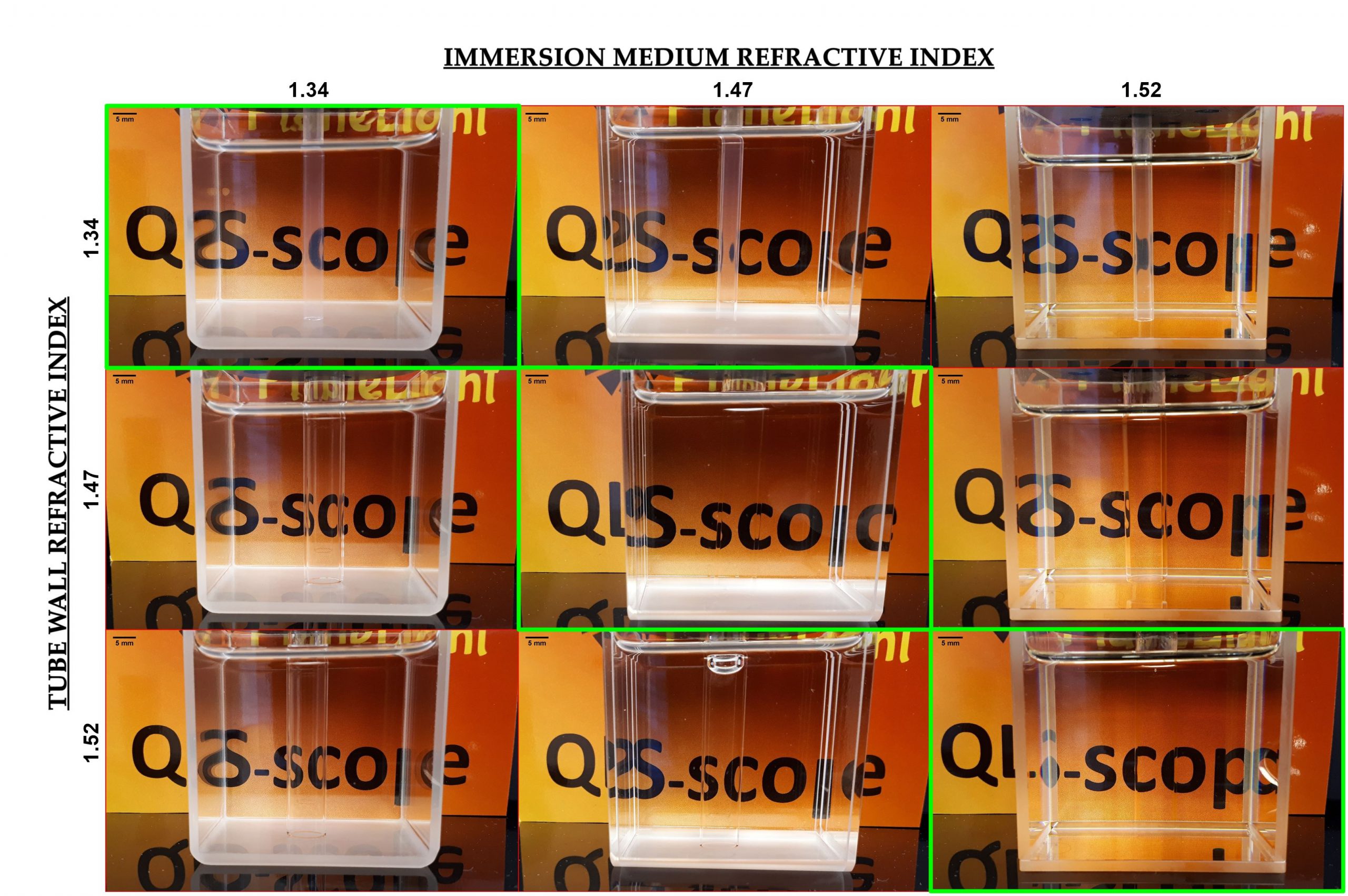
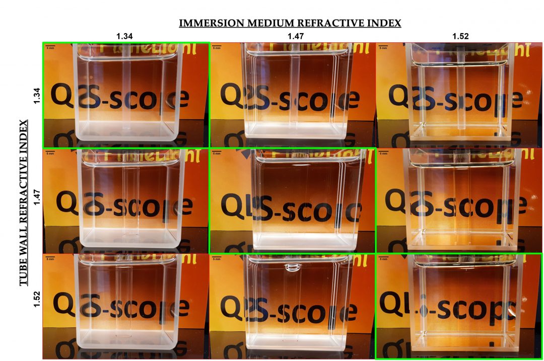
| Figure 1. Properly matching the refractive index of glassware and immersion fluids allows us to offer setups with excellent optical properties for most common clarification methods. The green panels show imaging chambers in which the tube holding the sample causes minimal refraction change, rendering it almost invisible and
without distortion. |

In microscopy, the path light travels to and from the sample determines the quality of the final image at several levels: if the excitation beam encounters dense spots or translucent areas, the intensity of the illumination will decrease and its focus may change. If fluorescence from excited fluorophores in the sample goes through media with heterogeneous refractive indexes (RI), the light will suffer refractive changes at each interface, degrading the image and decreasing resolution. To avoid these deleterious effects, modifications are incorporated in the optics (i.e. RI correction collars) which increase the cost and complexity of the devices. QLS-Scope solves this issue by employing especially designed imaging glassware and media that present a homogenous refractive index, irrespective of the clearing protocol used on the sample (Figure 1). They include tubes of different materials and diameters to accommodate any sample; their cylindrical section allows to rotate the sample to optimize positioning, as well as the application of SPIM-SPOT. In this application note we analyse the performance of such solution through 2 sets of experiments, comparing the net effect of different materials and geometries on image resolution.
EXPERIMENT 1: REFRACTIVE INDEX MISMATCH EFFECT
An integral part of QLS-Scope is the use of optical setups that adapt to the clearing protocol used. To determine how critical this feature is, we have compared resolution in tubes of similar dimensions but different material.
MATERIALS AND METHODS
1.9 micron fluorescent beads (Duke Scientific Corp., #G0200) were dispersed in molten 1% agarose at 1:50000 dilution. The resulting suspension was poured into a 4 mm ID (internal diameter) borosilicate tube (RI=1.47) and a 4 mm ID FEP tube (RI=1.34). The tubes were placed in a water filled transparent container and imaged using the Qscope mode of QLS-Scope under the following parameters: binning 2; 5x magnification (Mitutoyo 5x M Apo, NA 0.14); laser 488 nm at 60% power; filter 531/40BP; exposure 80 ms; 3 microns of Z-step (approximately 1600 slices).
For each sample, a SPIM was performed covering 4.8 mm in Z. From each dataset, 3 16-bit optical slices were selected at 15%, 50% and 85% of the range. In each frame, 15 separate beads were measured in both X and Y dimensions using the PLOT and CURVE FITTING[1] tools in ImageJ[2]. Pooled data were compared using a t-test.
RESULTS

| BS |
| FEP |
| Figure 2. RI effect on apparent bead size. The left panel shows the tubes being used for imaging. Measurement of fluorescent beads (n=45) through FEP or BS indicates that keeping a homogenous refractive index increases the resolution of the measurement, attaining a significant difference (p<0.05) in the Y dimension. |
Figure 2 shows the tubes used to perform the material comparison and the resulting data. The SPIM analysis in borosilicate and FEP tubes shows an apparent bead size close to 4 µm for both, although FEP produces data closer to the true size, supporting the advantage of having a RI-matched optical setup.
EXPERIMENT 2: INTERFACIAL GEOMETRY EFFECT
The use of cylindrical tubes in QLS-Scope provides significant advantages in terms of specimen handling and recovery, optimal positioning in the field of view and feasibility of 360º imaging. However, this design raises the issue of the effect of curves on image resolution, as they involve a varying position for the tube-medium interface relative to the objective.
MATERIALS AND METHODS
A similar bead suspension was poured into a 10 mm ID borosilicate tube (RI=1.47) and a 10 mm internal side cuvette (RI=1.47). The tubes (Figure 3)

| Round |
| Flat |
| Figure 3. Cylindrical and square section tubes used for interface geometry investigation. The containers present a similar RI but a different surface (round and flat, respectively) towards the detector. |
were placed in a water filled transparent container and imaged using the Qscope mode of QLS-Scope under the above listed parameters, using a 9 micron Z-step (approximately 1100 slices/SPIM).
Figure 4 describes the imaging chamber and data acquisition setup. For each sample, 3 SPIMs covering 10 mm in Z were performed with the tube at the centre of coordinates, 3 mm to the left and to the right in the X axis (C, L and R datasets, respectively). From each data set 3 16-bit optical slices were selected at 15% (BACK), 50% (MID) and 85% (FRONT) of the Z range. In each frame, 5 separate beads were measured in both X and Y dimensions using the PLOT and CURVE FITTING tools in ImageJ. Data from each position were compared using t-test (comparison
| Figure 4. QLS-Scope features a classical light sheet design, with orthogonal light and detection paths. The sample is kept suspended at the intersection within a RI-matched container that allows translation and rotation. A suspension of fluorescent beads was poured into a round section (orange outline) or square section (black outline) tube and imaged by SPIM at 9 different positions (white dots) to map possible changes in resolution. L, C, R: left, centre and right scanning positions. Back, Mid, Front: 15%, 50% and 85% positions within the Z range of scanning. S, specimen. |
between cuvette and tube) and ANOVA (among positions in the device).
RESULTS
Figure 5 summarizes the results of the comparative measurements. The pooled data for the whole tube or cuvette (n=45) shows that the apparent size of the particles in both systems is around 4 microns, although the flat cuvette shows a slightly smaller size (closer to the declared bead size) and less heterogeneity in the data. The differences, in favour of the flat cuvette, are non-significant for X (p≈0.072) and significant for Y measurements (p<0.005).

| Figure 5. Interface effect. 45 beads per tube were measured in both X and Y to compare the effect of a flat vs. round geometry in the tube wall. The absolute numbers are quite close, although the flat surface seems to produce less dispersion of the data. |
Based on the above described tube mapping, we compared bead apparent size in both systems, sub sampling the data for specific distances from the tube wall and the tube centre (9 regions per tube). The results show that the different geometries don´t affect the measurements dramatically, with sizes close to 4 microns across all regions. However, statistically significant differences (albeit minor in absolute value) were found in some specific regions (asterisks in Figure 6), always in favour of the flat tube, suggesting that geometry does in fact have a role in imaging.

When intrasystem (flat cuvette or round tube) variability is considered, ANOVA analysis of the 9 measured positions in each device shows that the round geometry of the tube wall does in fact cause heterogeneity in the resolution (p=0.03) when the Y dimension data are considered. No significant differences are found in the flat cuvette.
QLS-Scope supports the use of both tube geometries, so the user doesn´t have to commit to one, picking whichever suits its particular experiment.Based on these results, a flat container may provide better optical properties; however, the corners limit the points of view available for imaging to 4 (0º, 90º, 180º and 270º). On the other hand, a round geometry seems to have a minor optical effect, but it provides more freedom in terms of sample positioning, focusing and permits 360º imaging, which can be relevant and convenient when viewing large samples.

| Figure 6. Apparent bead size measured in 9 tube positions (intersection of green and red lines in the central graph). Measured values are generally lower for the flat cuvette, although the differences are only significant for those comparisons with asterisks. L, C, R: left, centre and right positions in the X dimension, respectively; Back, Mid and Front: farther, middle and closer positions in the Z dimension, respectively. |
[1] Apparent bead size is calculated from the adjustment of the data to a Gaussian distribution (y = a + (b-a)*exp(-(x-c)*(x-c)/(2*d*d)), where d*2.355=FWHM.
[2] Schindelin, J.; Arganda-Carreras, I. & Frise, E. et al. (2012), “Fiji: an open-source platform for biological-image analysis”, Nature methods 9(7): 676-682.
